AUTODESK
Creating new interactions for editing the vertical alignments of roads
InfraWorks | 2013 | Discovery-Delivery | Shipped Oct 2013InfraWorks is a new application in the civil engineering CAD suite
It fills the concept generation and presentation gaps in civil engineers’ application ecosystem. The roads and highways module enables civil engineers to quickly draw and visualize roads with rule-based geometry on top of their site’s topology, imported from their survey studies. This project solves three business goals:
Replace paper-based concept phases
Interoperable road feature sets between InfraWorks and Civil3D
Missing presentation suite
ROLE
UX Project Lead
CONTRIBUTION
Embedded into an Agile engineering team, I interviewed industry professionals, learned civil engineering, and designed the menus and 3D interactions

PROBLEM
How do you draw roads in a 3D workspace?
In current workflows, Civil Engineers use CAD applications like AutoCAD Civil3D to hand draw roads and all their attributes. InfraWorks introduces a 3D modeling experience that starts with an imported topology plane. What new and complementary toolsets for do civil engineers need in order to draw, edit, and view their roads in 3D?
When a roadway engineer has to adjust the vertical alignment of a roadway, they need to be able to add, remove, and edit Points of Vertical Intersection (PVIs) horizontally, vertically, and along a fixed slope as well as adjust the curve type, radius, and k-value of vertical curves, so that they can optimize their cut/fill, overhaul costs, and provide a safe driving experience.
How can we create tools that enhance the drawing and modeling experience to provide real-time rule-based feedback based on the project’s regional standards?
Every segment of a road is hand-drawn without the real-world feedback.
Viewing - Reimagine how to view large lengths of roadway so to:
Reduce the amount of panning in the workspace
Create a fixed place within the user interface they can always refer back to.
Update the traditional profile tool
Managing workspace views is a productivity papercut to the development cycle.
Roadway designers have multiple monitors and windows of the workspace at the same time. A profile view is the industry-standard tool for displaying and editing vertical alignments for roads, drainage, and other attributes that span the length of a road. When referring to different locations within the same drawing, they must manually navigate their profile view to their segment via wayfinding or discovery.
How can we modernize the profile view to reflect changes made in 3D?
Enhance the drawing experience so the Roadway designers can focus impact
OBJECTIVE
Managing workspace views is a productivity papercut to the development cycle.
Viewing - Reimagine how to view large lengths of roadway so to:
Reduce the amount of panning in the workspace
Create a fixed place within the user interface they can always refer back to.
Update the traditional profile tool
UX PROCESS FOR THIS PROJECT
Define the problem space
Refer to the American Association of State Highway and Transportation Officials Manual (a.k.a the AASHTO green book) to understand the technical details of vertical geometric curve design and its significance so when I talk with customers I sound some what intelligent.
Interview key customers about their work practice, current tools, and how they would improve upon the interface within InfraWorks.
Create a hypothesis.
Sketch a lot.
Hash over sketches with Team Pavo to gauge level of development effort and how to iterate on the design.
Schedule usability testing while functionality is built.
Conduct usability testing of beta functionality.
Iterate based on feedback.
Integrate into the main code base once users approved the functionality and the functionality met our set acceptance criteria.
Design
3D Manipulation Tools
CONCEPT
Initial sketches to understand the basic vertical curve geometry and gizmo problem space
As a team we had to consider the implications of having redundant grips for curve radius functionality. This sketch is my exploration on why we only needed two instead of three. We ended up using the position of the center grip to display the vertex of the curve.
Grip refinement
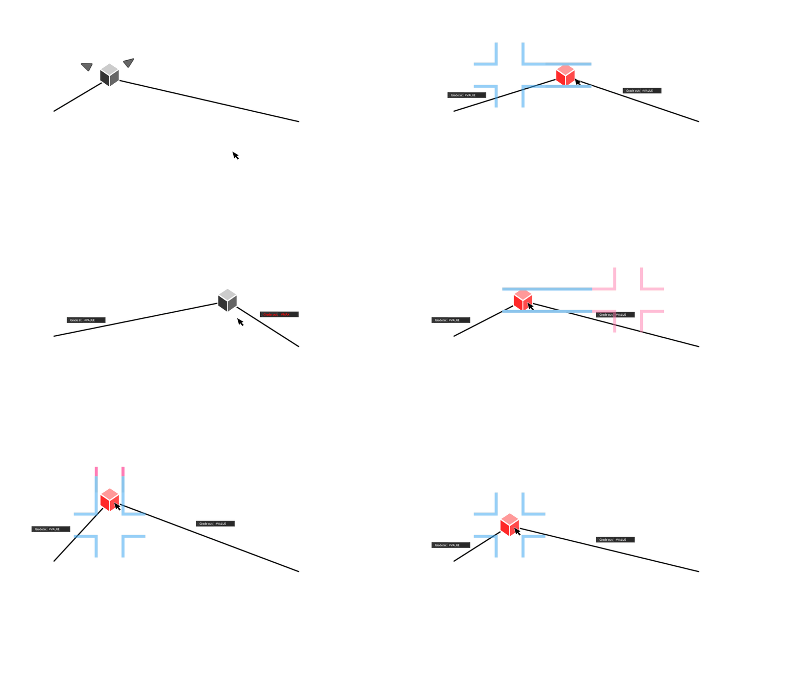
When a roadway designer is editing the position of a PVI, the PVI is constrained in four different ways. We decided we needed to provide guides and visual feedback to the designers for how the grip's movement is constrained as well as where can they put the grip without exceeding the maximum allowable slope for the road way.
The users either wants to maintain the station (length location along the roadway) and adjust the elevation of the PVI. The opposite, where they need to maintain elevation and adjust the station of the PVI. There are two cases where the roadway designer needs to maintain the slope of one tangent, either incoming or outgoing. In those cases the roadway designer wants to move the grip up and down along a tangent while the other tangent adjusts. The final case is when the roadway designer doesn’t really care about any of those constraints and just wants to place the PVI in roughly the right location. In that case they are adjusting both the station and elevation of the PVI at the same time.
In-context feedback study
When a roadway designer is editing the position of a PVI, the PVI is constrained in four different ways.
We decided we needed to provide guides and visual feedback to the designers for how the grip's movement is constrained as well as where can they put the grip without exceeding the maximum allowable slope for the road way. .
3D Mockups
I took these interactions and overlayed the grips onto a road alignment in 3D to demonstrate how the grips would work when a PVI is selected. Below we see exaggerated examples of the rest state, moving the PVI horiztonally and vertically along its constraints.
As a team we had to consider the implications of having redundant grips for curve radius functionality. This sketch is my exploration on why we only needed two instead of three. We ended up using the position of the center grip to display the vertex of the curve.
For this project I refactored the interaction designs from Civil3D's vertical alignment tools to fit within the context of InfraWorks, redesigned the information design for the context menus, created the in-world visual constraint guides, and conducted the concept validation and usability testing for the vertical alignment tools.
In model geometric guides
RESULT
In production, here we see the geometric guides surrounding the grip. When the user grabs one of the handles, the geometric guides will provide feedback based on their design standards policy.
Road profile drawings can be incredibly long
2D PROFILE GRAPH
When Roadway designers are working with vertical alignment profiles, the drawings can be incredibly long. To address this roads are broken up into segments and therefore different documents based on each segment. In a 3D model, to view the same data, the user would need to pan and scroll along the road way. How can we improve how the user accesses and views long alignments?
Pull from non-engineering sources
Inspiration
My team was inspired by Google Finance's stock performance profile. We appreciated how easy it was to zoom in and out of the profile to focus on a range of time. This direct correlated to how roadway designers complained about being unable to quickly refer to a specific station ranges in their road profiles.
What impressed me the most about the Google Finance financial profile was what we called the "range navigator" located at the bottom of the graph. It allows users to select a range of interests. For this effort, I adapted and refactored their profile design to provide roadway designers greater access to vertical alignment geometry.
Putting it all together
Starting with GIS Data
Here we have an example of South Lake Union in Seattle, with GIS data from 2013. This example is walks though how a road designer would adjust the vertical alignment of Mercer Street near the I-5 enterance ramp using both in-scene direct manipulation as well as the profile view.
Edit Mode
When we take a look at the vertical alignment by selecting on the road and rotating the view to a more profile-esque view we are able to see the vertical alignment grips and the vertical alignment geometry. If we wanted to take a closer look at a PVI in the profile view, I created a mirrored interaction where the user can click on either the PVI in-world or in profile and get a closer more in-depth view of that point.
Inspecting the profile
Here we see the PVI selected and highlighted in both the profile and in-world.
Adjusting the Alignment
If the road designer wanted to edit the location or properties of the curve, they could either do it in-world in the context of the environment, or they can use the profile view to get a more accurate position. Here we see the user adjusting the elevation of a PVI while maintaining the station for that PVI. When a user edits a PVI either in profile or in-world, both update dynamically to provide the user with as much information as possible.
Want to Learn More?
Shoot me an email! Let’s discuss your questions, comments, and organizational needs.


